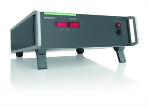
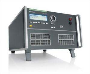
Transient Immunity Test Generator as per FORD ES-XW7T-1A278-AC


RCB 200 - Generation of relay switching transients
This RCB 200 relay switch box has been designed by EM TEST to offer a high-quality solution for customers testing according to ES-XW7T-1A278-AC Ford specification.
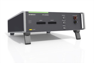
Three function keys permit to operate the unit, to select the test pulses and test modes.
- TEST allows to start and to stop the test
- PULSE allows to select the pulse
- MODE allows to select the mode for Pulse A1, A2, B1, B2 and C
LEDs indicated the selected pulse and mode.
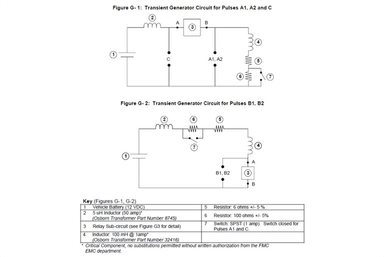
- As per Ford ES-XW7T-1A278-AC, Annex G, Figs. G-1/G-2
- Pulses CI 220: Pulses A1, A2, B1, B2 and C
- Pulse CI 260: Pulse F
- Strictly using components as per Ford requirements
- Fixed repetition times and pseudo-random timing
- Automatic control of mode and switch settings by micro-controller
- Easy control by manual operation
Benefits
Micro-processor controlled RCB 200 ensures easy operation
With its 6 different pulses and two different modes to sequence these test pulses the RCB 200 is easily operated by only three function keys. A micro-controller automatically sets the circuit required to generate the selected pulse in the predifined mode (fixed mode with specified repetition and duty cycle (pulses A1, A2, B1 and B2) or random (pulse C)).
The RCB 200 can also be used for tests as per CI 260F.
Test modes 2 and 3are based on a pseudo-random timing of the application of pulses. This is done automatically by the built-in microprocessor. All tests can be performed in sequence or endless.
The Potter & Brumfield relay must be replaced because of the life and wear after 100 hours of tests. An integrated counter actively monitors the operating time of the relay. The EOL LED (end of life) indicates the current EOL status.
Details for Relay Circuit
RCB 200 - strictly designed as per ES-XW7T-1A278-AC
 Transient Generator Ford ES-XW7T-1A278-AC
The circuitry of the RCB 200 is strictly following the requirements as per Ford given in Annex G, Figs. G-1 and G-2 for transient pulses A1, A2, B1, B2 and C, using the components specified by Ford.
The two test modes are achieved based on the relay circuit details given in Figs. G-3 and G-4 of Annex G.
ISO 7637-2:2011
Related Products
Automotive Transient Emission Measurements as per ISO 7637-2
Model : Transient Emission Set-iso-7637-2
Automotive Power Fail Simulator for OEM LV 124 and LV 148 an...
Model : PFM 200N100.1
Voltage Drop Simulator - Battery supply simulation and DC vo...
Model : VDS 200N
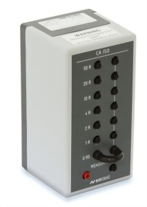
Calibration set for automotive transients
Model : CA ISO
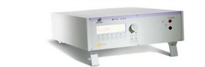
Micropulse Generator
Model : MPG 200S20