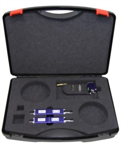
Calibration Target and verification adapter for ESD

ESD calibration target
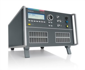
The CTR 2 is a coaxial current target to monitor Electro Static Discharges built as required by EN/IEC 61000-4-2 Ed.2 standard. The target can be purchased as an option to the ESD generators, model dito or ESD 30.
It can be used for measurements up to 30kV. Additional attenuators are available to match the output signal with the input capability of the oscilloscope.
- Current target as per IEC/EN 61000-4-2
- 2Ohm impedance +/- 5%
- Test voltage up to 30kV
- Insertion loss +/- 0.5dB up to 1GHz
- Insertion loss +/- 1.2dB up to 4GHz
- Includes 20dB attenuator and 1m cable RG400
- Additional attenuators available (optional)
- 50ohm Adapter line CTR 2-AD available (option)
Verification set-up for the CTR 2 Target
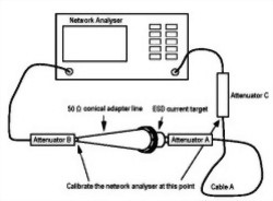
The current target is verified to meet the required insertion loss of +/-0.5dB up to 1GHz and +/-1.2dB up to 4 GHz.
In addition to the current monitor, a Huber&Suhner 2W/20dB attenuator with a 1m Huber&Suhner coaxial cable with type "RG400" connectors are used.
The ESD target, Attenuator A and Cable C form the so-called "Target-Attenuator-Cable" chain being calibrated in this set-up. Attenuators B and C may not be required.
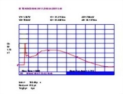
Insertion loss
S21 Measurement of the CTR 2 Target
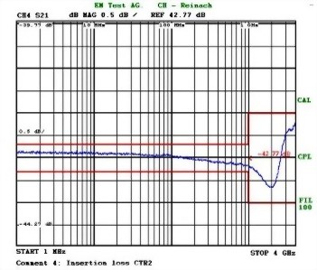
This figure gives the typical insertion loss characteristic of the "Target-Attenuator-Cable" chain.
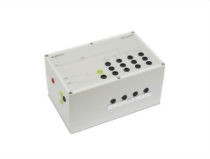
CTR 2-AD 50 ohm conical adapter line
50 ohm adapter line to calibrate the CTR 2 target
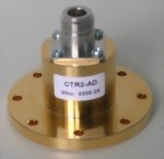
The 50ohm conical adapter line connects the 50ohm cable to the input of the CTR 2 target. Geometrically it smoothly expands from the diameter of the 50ohm coaxial cable to the diameter of the target. If the target is made such that the impedance calculated from the diameter ratio d/D (refer to figure A2 of the IEC/EN 61000-4-2 standard document) not being equal to 50, the target adapter line shall be made such that the outer diameter of its inner conductor equals the diameter of the inner electrode of the current target.
The impedance is calculated considering the dielectric constant of the material that fills the conical adapter line (typically air).
The target adapter line shall show an impedance of 50ohm +/-2% from DC to 4GHz. The reflection coefficient of two target adapter lines mounted face-to-face shall be better than 30dB up to 1GHz and better than 20dB up to 4GHz while the insertion loss shall be less than 0.3dB in the same configuration.
ESD Waveform Verification
How to verify the ESD pulses?
EM TEST recommends the following equipment in line with the IEC/EN 61000-4-2 standards requirements:
- DSO with a bandwidth of at least 2GHz
- Faraday cage
- EM TEST CTR 2 target
Capturing the correct waveform with the scope can only be achieved with the proper settings of the DSO. The settings need to be made to measure pulses with +/-2kV, +/-4kV, +/-6kV and +/-8kV. Four parameters need to be measured at each voltage level:
- Initial peak current
- Rise time between 10% and 90% of the initial peak
- Current value at 30ns
- Current value at 60ns
The time domain for the initial peak and rise time measurement is recommended to be set to 1ns/Div. For the current measurement at 30nS and 60ns a setting of 10ns/Div is recommended as being appropriate.
Measuring Set-up
Pulse verification set-up using a shielded room
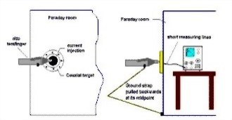
This figure illustrates the proper set-up of the measuring equipment, the CTR 2 target and the ESD generator to be verified.
Please observe that the ground return cable shall be pulled backwards at its mid point to form a large loop.
This is of high importance as the ground return cable may heavily influence the ESD pulses, especially at the measuring point at 30ns and 60ns. If this fact is not properly observed you may see oscillations on the scope disturbing the pulse characteristic.
How to calculate the ratio?
Relationship between peak current value and measured peak voltage
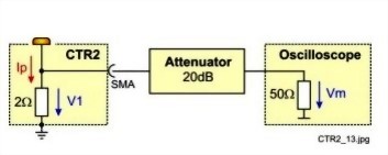
Calculated from the impedance and attenuation values the following equation gives the proper ratio:
Ip = 5 x Vm
where
Vm is the voltage signal measured by the DSO in Volt
V1 is the voltage measured accros the CTR 2 target
Ip is the discharge current
Therefore
V1 = 20dB x Vm = 2ohm x Ip
Ip = 20dB x Vm/2ohm
For example:
A discharge current of 7.5A will give a voltage reading of 1.5V on the DSO.
IEC 61000-4-2
ISO 10605
Related Products
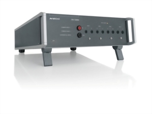
Coupling/decoupling networks for 4 signal/data lines
Model : CNV 504N5 series
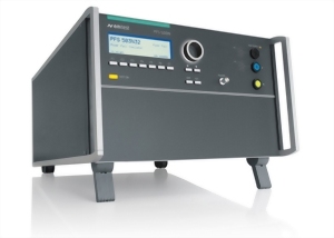
Power Fail Simulators
Model : PFS 503N series
Load resistors for EFT/burst verification
Model : CA EFT KIT
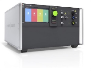
Multifunctional test generator for transients (EFT/Burst, Su...
Model : Compact NX7 Series
Coupling/decoupling networks for 4 pairs/8 lines as per IEC ...
Model : CNV 508N4-series